Saturday, November 15, 2008

Final Tutorial


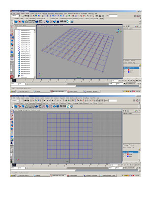
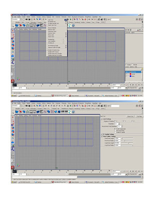
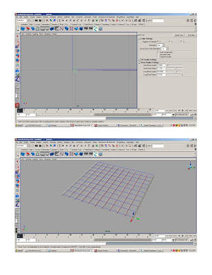
1.Create a NURBS circle, radius = 1, scale the circle to 50x50.
2.Scale the CV to square off the circle.
3.Change the frames from 24 to 200.
4.In the channel editor go to channels > key all circle at 1. A red line should appear at the number one on the time slider.
5.Move the time slider to 200. Translate the circle to 200 on the z-axis. In the channel editor go to channels > key all the circle at 200. A red line should appear at the number 200 on the time slider.
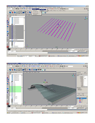
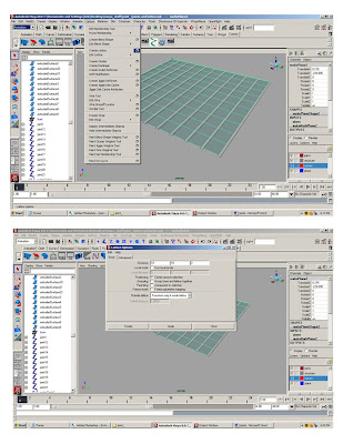
6.In the animation menu go to animation> Create Animation Snapshot click on the box.
7.In the Create Animation Snapshot window select Time Slider, change the increments to 12.00 and select Fast Up Date on Demand.
8.A snap shot group should appear in the options window. Create 5 layers: structure, glass, slabs, snapshot and circle. Put the stuff on the right layers.
9.Turn off the snapshot layer. Select the circle. Go to the surface menu. Select surface>planer click on the box.
10.Select polygons, quads, standard fit, and turn the sliders on the bottom of the window all the way down.
11.Extrude the polygon surface .337, use the “local translate z” for an exact measure.
12.Select the extruded polygon surface. In the animation menu go to animation> Create 13.Animation Snapshot click on the box.
14.In the Create Animation Snapshot window select Time Slider, change the increments to 12.00 and select Fast Up Date on Demand.
15.Put the snapshot in the slab layer and turn it off. Open the layer with the snap shot of circles.
16.In the surface menu, go to surface>loft, click on the box. Select NURBS and make the section span= 2
17. Put lofted surface on glass layer. Close snapshot layer.
18.Select the lofted surface. In the surface menu go to edit curve>duplicate surface curve.
19.In the side view, select the horizontal curves and delete them. (Or put them on a layer and turn them off—you can always use them for something else.)
20.Create a NURBS circle, scale the circle to .337, and extrude the circle along the vertical curves (Just like tutorial 3).
21.Put all those extruded surfaces and vertical curves on the layer structure.
22.Turn all the layers on. In the options window select the original circle. Move the time slider all the way to 200.
23.Scale the circle on the x to 30.24.Rotate it on the z 4525.In the channel editor go to channels > key all
26.Put a plane underneath the tower and render it.


Saturday, November 1, 2008

Surface and Volume Project.

Surface and Volume Project Due 11/22/08

For the next project you will design a surface that unifies 5 volumes.

The Parameters:

Create 5 volumes each at 1000 cubed feet. Arrange these volumes no less than 5 5ft apart from one another on a ground plane.

Create a object no larger than 1 cubic foot. This should be a reasonable simple object, derived from your inspirational image.

Use the object as a base in an aggregation to create a seamless continuous envelope around the 5 volumes.

In this project you must used various deformers, such as the lattice, joints, blend shape allong with the use of the non-linear deformers.

Animative techniques must be deminstrated in the formal generation of this project.

This project should be thought as an architectural pavilion- it should have a circulation, and loose program.

Use a 3D person to give scale to the project.

Deliverables:1- 3 perspectives of the pavilion. Each perspective should be shown as a 1 wire frame print screen, 1 shaded print screen, 1 Maya software rendering using the GI system, 1 mental ray rendering using ambient occlusion, 1 vector rendering, and 1 maxwell rendering. 18 images in all in a PowerPoint presentation- with one image per page, full bleed, no text.2- The Maya file.

Saturday, October 25, 2008

Tutorial 6 Joints and Lattice


Joints
1.Set scene to feet and set camera’s clip plane.
2.Do tutorial 3- the responsive structure.
3.Go to the animation menu.
4.Go to the top view.
5.Engage click to grid
6.Go to skeleton-joint-click on box
7.Rset joint tool
8.Click joint tool on top of structure at every curve
9. Select joints in options window and ‘ctrl d’
10. Move to next structural beam
11. Repeat until joints are on all structural beams
12.Go to Skin-bind skin- smooth bind
13. Select joints put on new layer
14. select any joint and move

Lattice.
1.Do tutorial 3 again
2. Select the plane
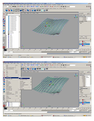
3. Go to Deform- create lattice- click box
4. In ‘divisions’ enter 10 10 and 2, this is the x, y and z
5. Select the lattice in the options window ‘ffd1Lattice’, right click and select ‘lattice points’.
6. Move the lattice points around and see everything move.

Delete the lattice, and the deformed object will go back to its original state.
or
Select the plane goto Edit>Delete by Type>History, and the object will stay deformed, but the lattice will be removed.


Create other objects and apply joints and lattices to see how the objects deform.


Saturday, October 4, 2008

Rendering Tutorial


MAYA SOFTWARE:

Open the cube tutorial
Make a new cube and scale it on the x and y to 50’ by 50’, use it for a plane under the cubes
Open the hypershader and create a phong, blinn and lambert.
Adjust the colors and transparency of materials.
Apply the materials randomly to the cubes.

Import the GI lighting system.
File>import>GI lighting system.
Select the imported GI lighting system groups in the options window and press ctrl G to group the GI Lights. Scale the lights out and surround the cubes.

Create a directional light, scale it move it up and duplicate it. Move the duplicate light over and rotate it towards the cubes. Go to the attribute editor of the duplicate directional light, scroll down and open the shadow tab. Click on the ‘use depth map shadows’. Adjust the resolution to over 512.

Select the perspective camera in the option window, open the attribute editor for the camera, and open the environment tab. Adjust the color to white.

Open the render settings window.
Under the ‘common’ tab adjust the image size to 640x480, and adjust the resolution to 200.
Under the Maya software tab, change the “quality’ to “production quality”, open the ray trace tab and click the ray trace box.

Render the scene

When the render is finished, save the render as a jpeg.

Save the file.

AMBIENT OCULSSION:

Open the cube tutorial and make three new materials.
Adjust the color and transparency of materials.

Select the perspective camera in the option window, open the attribute editor for the camera, and open the environment tab. Adjust the color to white.


Right click the mouse on “crate maya node” box and select “create mental ray node”.

Open the “textures” tab, and middle click the mouse on “mb_amb_occlusion”, hold down the middle button, and drag over to one of the materials. Select “ambient color” from the list. Double click on the “mb_amb_occlusion”, and in the attribute editor increase the samples to 512. Repeat for all materials.
Apply the materials to the cubes.
Open the render settings window.
In the “render using:” box select “mental ray”
Under the ‘common’ tab adjust the image size to 640x480, and adjust the resolution to 200.
Click on the Mental Ray tab, and change the production preset box to “Production”

Render

Save render as jpeg.

Save file.

Maxwell rendering:

Open the cube tutorial
Make a new cube and scale it on the x and y to 50’ by 50’, use it for a plane under the cubes

Go to window> settings and preferences > plug-in manager and click on all the boxes, and click refresh.

Open the hypershader and create three Maxwell materials.
Double click on the Maxwell materiasl and use the wizard to create a glass and car paint and plastic.
Apply the materials to the cubes.

Open the render settings window.
In the “render using:” box select “Maxwell”
Under the ‘common’ tab adjust the image size to 640x480, and adjust the resolution to 200.

Click on the “Maxwell” tab.

Increase the time to 20 minutes
Increase the samples to 1000

Click on the “Environment” tab.
Click on sky options

The physical sky will create a realistic sky, and is controlled with the various controls.
At minimum adjust the hour and click on the enable sun.

The sky dome will create a blank background-- adjust the color.

Render the scene.
The Maxwell render window will start up. When it starts you can go back to the maya file and continue working.

When the Maxwell rendering is finished, save the file as a jpeg.

VECTOR RENDERING:

Select the perspective camera in the option window, open the attribute editor for the camera, and open the environment tab. Adjust the color to white.

Open the render settings window and select Maya Vector in the render using box.
In the image format box, select “encapsulated postscript (eps)”.
Change the image size to the 320x240 preset, in the preset window.

Click on the Maya Vector tab.
Change the “Detail level preset” window to “high”

Click the fill objects box off

Click the include edges box on

Change the “Render optimization” box to “Good”

Render the scene.

When the render is complete you need to open the eps file in either Illustrator or Photoshop. The eps file will be deep in the Maya files and the path will be on the common tab of the render settings window.
It looks like this:
Path:C:/Documents and Settings/your name/Documents/maya/projects/default/scenes//


In Illustrator or Photoshop overlap the vector on other renders